
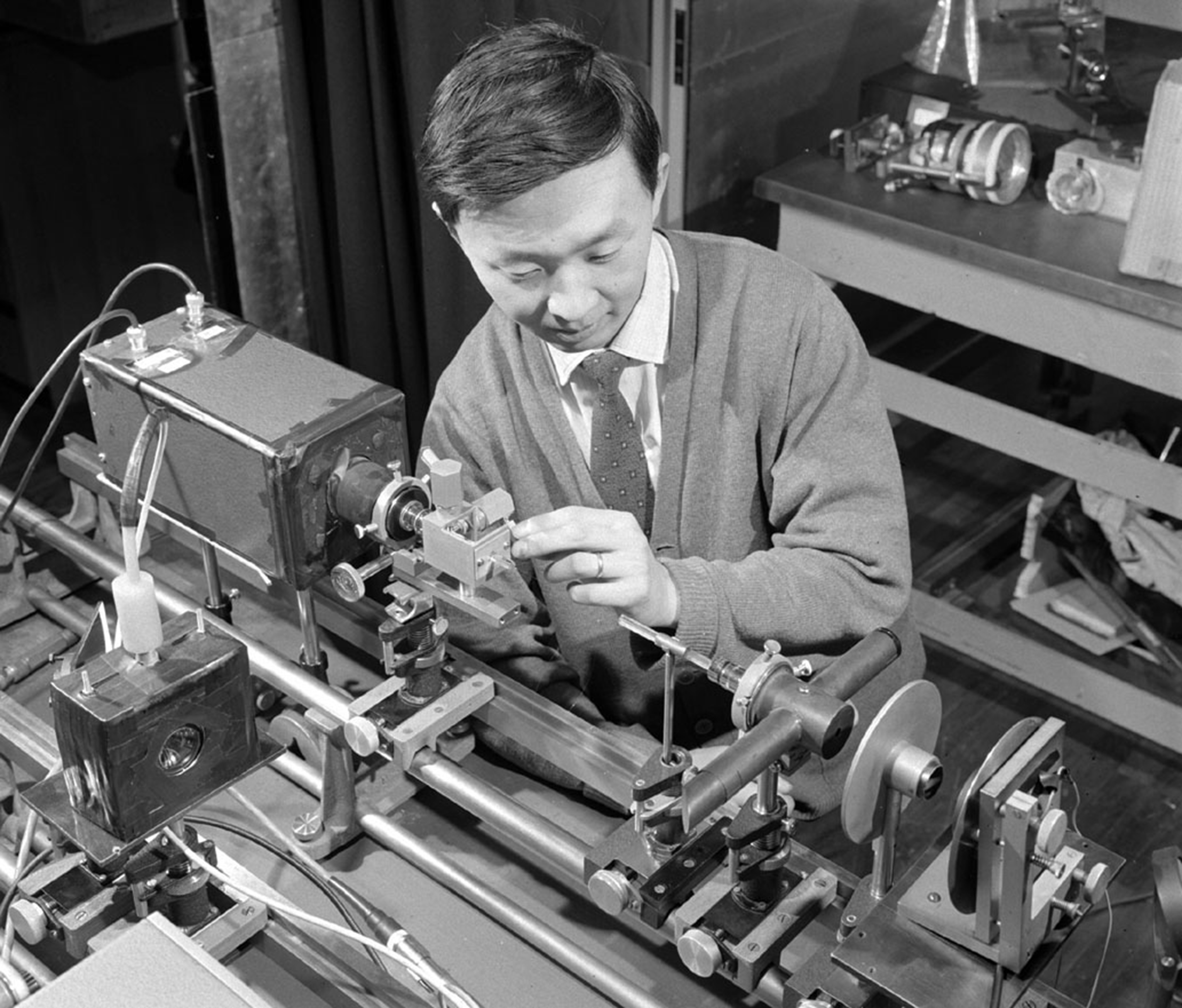
Early developments in optical fiber
Charles Kao’s idea that high purity fused silica would allow transmission of data through a fiber was proven in 1970. By 1973, researchers at Bell Labs developed the MCVD process to make preforms using Heraeus fused quartz tubes. Layers of high purity fused silica were deposited on the inside of the tubes before they were finally collapsed to obtain the preform. The initial preforms were very small with an outer diameter of between 20- and 30-mm. Little more than a few hundred meters of fiber were produced in a single batch.
Heraeus high purity tubes were used for both, the substrate tubes for the MCVD process and as the jacket tube. In the early 1990's, Heraeus introduced synthetic fused silica tubes to the market. These tubes have developed into the industry standard for fiber production because of their excellent geometric properties, surface quality and chemical purity.
Since the beginning of the industry and especially after the industry crisis in 2002, preform size has continually increased to lower costs. Heraeus introduced the RIC® process, achieving the world largest preforms. From a single preform with an outer diameter of 200 mm and a length of 3 meters over 7000 km of single-mode fiber can be drawn. This evolution in size has contributed to lower production costs and therefore contributed significantly to the success of fiber optic networks.
How do optical fibers work?
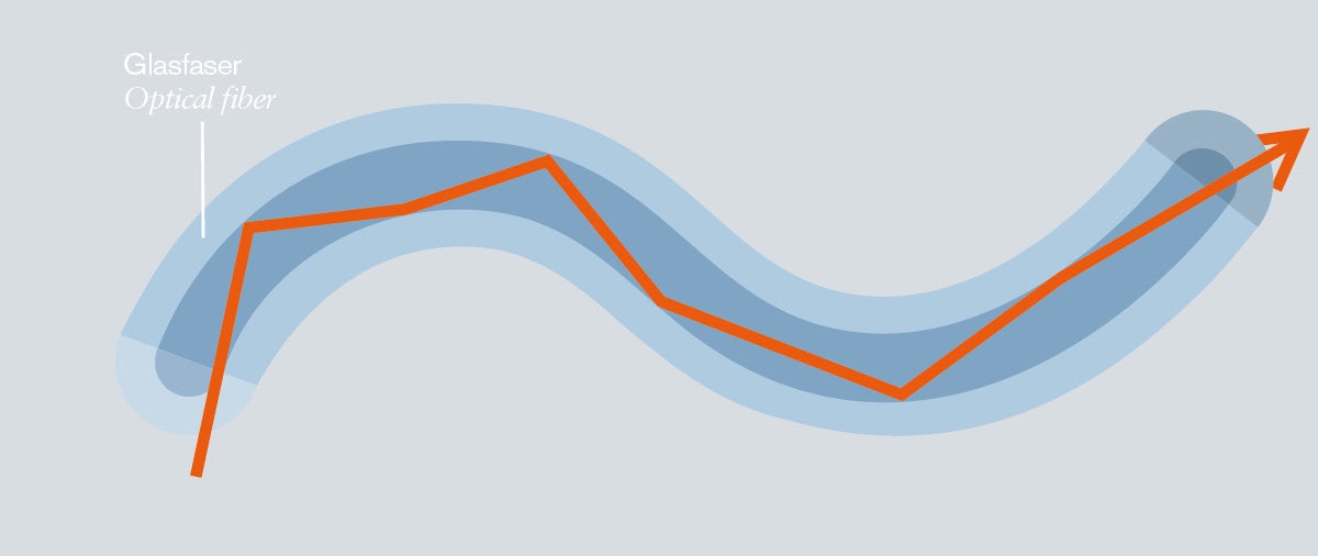
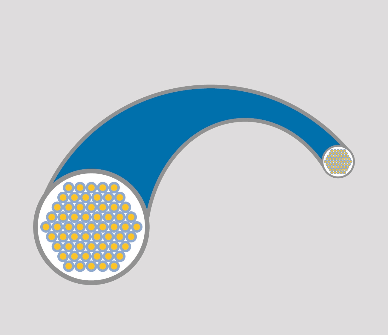
Optical fibers consist of a light guiding core and a cladding. The core must have a higher refractive index than the surrounding cladding so that the light internally reflects at the interface between core and cladding. This reflection guides the light along the length of the fiber with extremely low attenuation. The important properties are the difference in refractive index and the NA (numerical aperture) of the fiber which is the angle under which light that enters one end of the fiber is still guided to the end. There are numerous possibilities for optical fiber designs and applications, from large volume standardized telecommunication fiber to very individual designs that serve one customer in a specific application.
Custom designed optical fibers
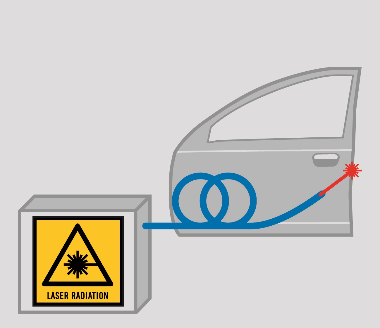
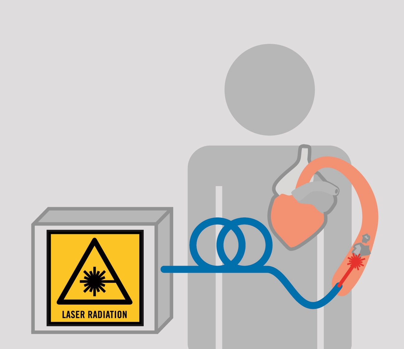
Many applications require the transportation of light from one location to another without line of sight, or where it is impractical or dangerous to have an open beam. In this case an optical fiber is the ideal solution because it can bend and move, yet keep the two locations connected. A few examples of these applications include medical and spectroscopic applications as well as material processing.
For each application the right optical fiber depends on its transmission characteristics and the shape of the beam that exits the fiber. These two properties depend on the refractive index profile, material composition and geometrical shape of a fiber. Learn more about how these parameters influence the transmission in the details below. While these three properties represent a high degree of freedom to realize the customer needs, a lot of knowledge is necessary to achieve the optimal solution.
Optical fibers for laser processing
Automotive applications (laser cutting and welding)
Fiber bundles
Specialty fiber bundles (e.g. beam homogenization for photolithography and spot curing of UV adhesives)
Optical fibers for medical applications
Medical laser surgery (e.g. ablation of arterial blockage or vaporization of prostate tissue to treat BPH)
Optical fibers for spectroscopy
Spectroscopy from UV, to VIS, to NIR ranges

Preform design
A preform is a bigger solid version of a fiber. The fiber is drawn from the preform and should have all the properties the preform had. The minimum requirement of a preform is that its center, which later forms the core of the fiber, is made of a glass with a higher refractive index than the glass that makes up the cladding.
In essence, the performance of the fiber depends on the material composition, the geometry and the refractive index of the different layers. At Heraeus we combine our accumulated fused silica know-how and processes that we combine to realize your ideas.
Material composition
Pure fused silica without any impurities has excellent transmission over a broad spectral range. Doping can modify transmission but can also be effected by unwanted impurities. Furthermore, dedicated doping can modify the refractive index of the material.
For example, a material with high hydroxyl content is the material of choice for transmission in the UV range. For transmission in infra-red wavelengths, a material with low hydroxyl content is required.
Furthermore, using rare earth elements for doping in the core of a fiber can amplify the light. These fibers are called active fiber or laser fiber.
Refractive index profile
To transmit light through a waveguide requires a two-layer structure first. A core with a higher refractive index than the outer cladding. This can be achieved either by doping the core with elements which increase the refractive index, e.g. with germanium like in telecommunication fibers, or by doping the cladding with elements like fluorine which lowers the refractive index.
The height of the refractive index step defines how confined the guided light is in the core and how many different modes (pathways of the light through the fiber) there are.
The layer thickness of the cladding also influences the guiding properties as always some light penetrates into the cladding. If the layer is too thin some light gets lost, especially if the fiber is bent.
In modern designs the refractive index profile shows several layers with different optical functions, e.g. to create a ring shape instead of a single spot or to create a pump cladding for laser fibers.
Geometry
The geometry is another factor defining the transmission properties. Some examples are given below:
Shape
A square shaped core in a multi-mode fiber will cause a mixing of the different light modes transmitted. Therefore the light energy density of the cross section of this fiber will be more homogenous.
Laser fibers often use an unsymmetrical cladding for guiding the pump light. The broken symmetry suppresses helix modes and increases the pump efficiency.Distances
The layer thickness within a fiber design determines whether the light is guided or stripped off. A thin layer, for example, is useful for stripping some unwanted modes of light.
In polarization, fiber stress elements maintain a position beside the core. These often boron doped elements have a different thermal expansion and introduce therefore a mechanical stress which modifies the transmission properties. The distance of the stress elements from the core influence the amount of stress.
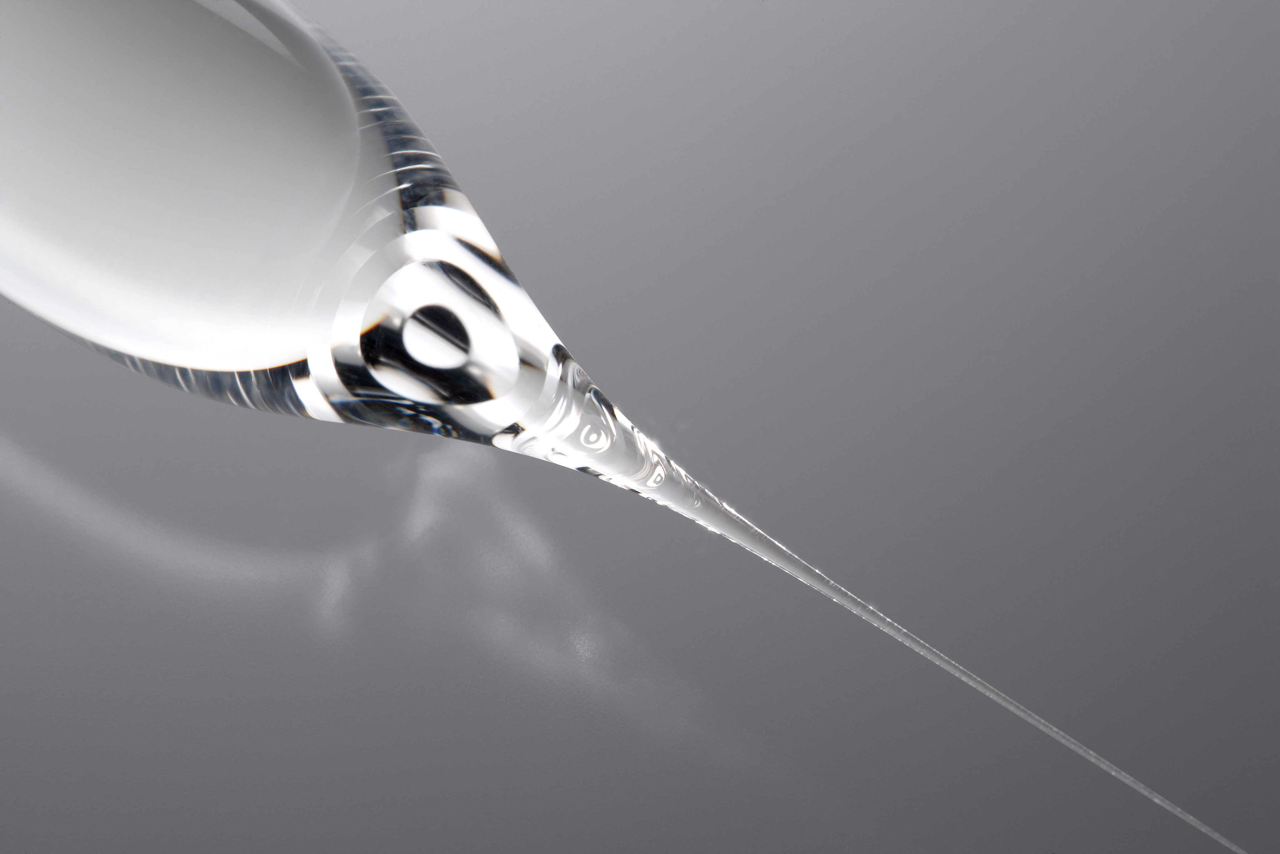
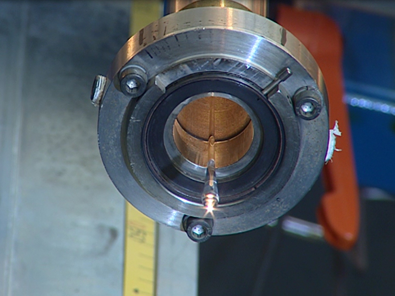
Fiber draw
Optical fibers are produced on a draw tower. The tower can be as high as 30 m and consists of a holding and feeding mechanism for the preform, a furnace, measurement devices, a coating apparatus, curing light sources and a take up spool.
The speed of the fiber draw depends on the preform, fiber type and available equipment. It can be a few meters per minute up to 2500 meters per minute for up to date telecommunication fiber production.
Post draw processing
The geometric properties (diameter, ovality) are controlled during the draw process. After drawing optical fibers are tested to verify all other properties are within the specification.
These properties can include any of the following: attenuation, macrobend attenuation, cut-off wavelength, mode field diameter, dispersion, polarization mode dispersion, tensile proof test, glass geometry (curl, cladding diameter, core-clad concentricity, & cladding non-circularity), and coating geometry (coating diameter & coating-cladding concentricity).
In single-mode production, the first test typically is a strength test. Then optical properties like attenuation are measured. For the next process steps, fibers are cut to predefined length.
If a cable contains multiple fibers, they usually have received an additional color coating to allow for easier identification. To color code and mark the optical fibers, UV curing paints are applied and cured within seconds with UV radiation. Take advantage of the Heraeus UV experts to select the right UV solution tailored to your process.
Also typically a cabled fiber gets a connector at both ends and the end faces are polished. For other applications several fibers are fixed together in one connector to create a flexible fiber bundle.
Typically there are two major steps in preform production. First the production of the light-guiding core and possibly a first cladding, to produce what is called a core rod. In a second step, the cladding is produced either separately or directly on the core rod.
Core rod processes
- For large batch size, telecommunication fibers, VAD, OVD and PCVD are the most common processes to produce the core of an optical fiber.
- Smaller batch sizes used are MCVD and FCVD.
- A solid glass rod is bought and used as is.
Cladding processes
- Overcladding the core rod with a glass tube, a so called jacket tube with a different refractive index. This process is often called the “rod in tube” or RIT process.
Depositing glass directly onto the core rod. Heraeus offers this process as a service.
